ANSWER TO REVIEW QUESTION 1
Section B-B shows the slope as 2:1, which is the ratio of horizontal to vertical distance. Therefore, horizontal
distance/vertical distance = 2/1. (para 3-2)(fig 3-1)
Horizontal distance
8 feet
Vertical distance =
=
= 4 feet
2
2
ANSWER TO REVIEW QUESTION 2
The schedule shows a 21,000-gallon tank to be type III. Under the section labeled "tower" and in the steel beam
column, it can be seen that the beam and spacing to be used is wide-flange; 1' -8" OC. (para 3-4, a) (fig 3-3)
Section II. Plumbing
up to 12 inches in diameter is referred to by its
3-5.
DEFINITION
nominal size, which is approximately equal to the
All piping, apparatus, and fixtures for water
inside diameter. The exact inside diameter will
distribution and waste disposal within a building is
depend on the grade of
classified as plumbing. Piping for heating systems is
called "steam fitting."
3-6.
PLUMBING PLANS
As a rule, plumbing plans show the location of
fixtures and fittings to be installed and the size and
routing of piping. Details are left to the plumber who
is responsible for installing a properly connected
system in accordance with good plumbing and
construction practices.
Plumbing plans consist
generally of four types of symbols.
(1) line symbols for piping;
(2) pipe-fitting symbols for pipe unions,
couplings, and connections;
(3) valve symbols to indicate the required
control points in the system; and
(4) symbols
indicating
the
various
plumbing fixtures required by the plan. Before trying
to read a plumbing plan, you should familiarize
yourself with the symbols shown on figures 3-5
through 3-8 and with the explanation of these
symbols given 'in the following paragraphs.
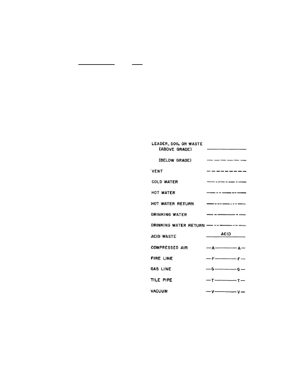
a. Piping Symbols. The type and location of
piping will be indicated on the plans by a solid or
dashed line. Figure 3-5 shows the standard symbols
Figure 3-5. Line symbols for piping.
used on piping diagrams. The size of required piping
will be noted alongside each leg on the plan; an
example of sizing can be seen on figure 3-6. Piping
108


 Previous Page
