round bars are placed around the vertical bars.
(2) Read the elevation and plan sections of
the reinforced concrete pier in figure 2-21. Note that
the pier consists of a post that is 12 inches square on
a footing measuring 2 feet, 8 inches square and 1 foot
(minimum) in depth. The post reinforcement consists
of four vertical, 3/4-inch diameter round bars on 9-
inch centers, with 1/4-inch diameter round bar hoops
at specified intervals (designated on the print or in the
reinforcing schedule). The footing reinforcement
consists of eight 3/8-inch diameter round bars
arranged as a mat.
(3) The elevation section of a reinforced
foundation wall (fig 2-21) shows vertical, horizontal,
and longitudinal bars. Note that the wall thickness is
designated by the letter "A" minimum.
An
explanatory note on figure 2-21 advises that the
thickness of the wall and the size of the footing
depends upon the soil bearing capacity and weight
load.
This note also reveals that minimum
temperature and building codes determine the depth
below ground of a reinforced foundation wall. The
vertical bars are 1/2-inch diameter round bars spaced
at 9 inches center-to-center and the longitudinal bars
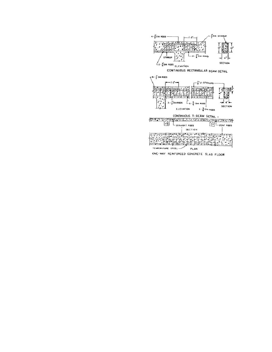
Figure 2-22. Reinforcement details for beam and
are 1/2-inch diameter round bars spaced at 18 inches
slab floors.
center-to-center. The horizontal bars in the footing
are not specified in figure 2-21, but will be found
bars in portions of a continuous rectangular beam, a
elsewhere in associated plans.
continuous T-beam, and a span of one-way
reinforced concrete slab floor. For example, you can
(4) In viewing the section of a reinforced
see that the continuous rectangular beam will be
retaining wall shown in figure 2-21, you will find the
reinforced with 4 1/2-inch diameter truss bars, 2 3/4-
thickness and height of the wall and the height and
inch diameter straight rods, and 1/2-inch diameter
width of the footing. You will also learn that the
stirrups. You should also note that the cross-section
backfill of the wall is porous, a 4-inch tile drain is
size of the beam is 6 x 12 inches. Beam length is
provided, and the longitudinal reinforcement bars are
given in the associated schedule.
to be 3/4 inch round. Note that the wall thickness
increases from a thickness of 7 inches at the top to 1
2-15. JOINTS AND CONNECTIONS
foot at the bottom. Data not given in this section,
such as bar lengths and degree of bends, as well as
The manner in which structural members and
radius of hoops and spacing, is supplied in the plans
construction materials are connected to each other is
and schedules of the structure.
shown in detail drawings.
(5) An inspection of figure 2-22 will show
a. Foundation Walls. Foundation walls are
you
the shapes and locations of the steel
bonded to footings with vertical reinforcing bars
called dowels, which are placed in footings and
extend upward 3 to 4 feet into the wall (fig 2-21). A
wedge-shaped trough,
66


 Previous Page
