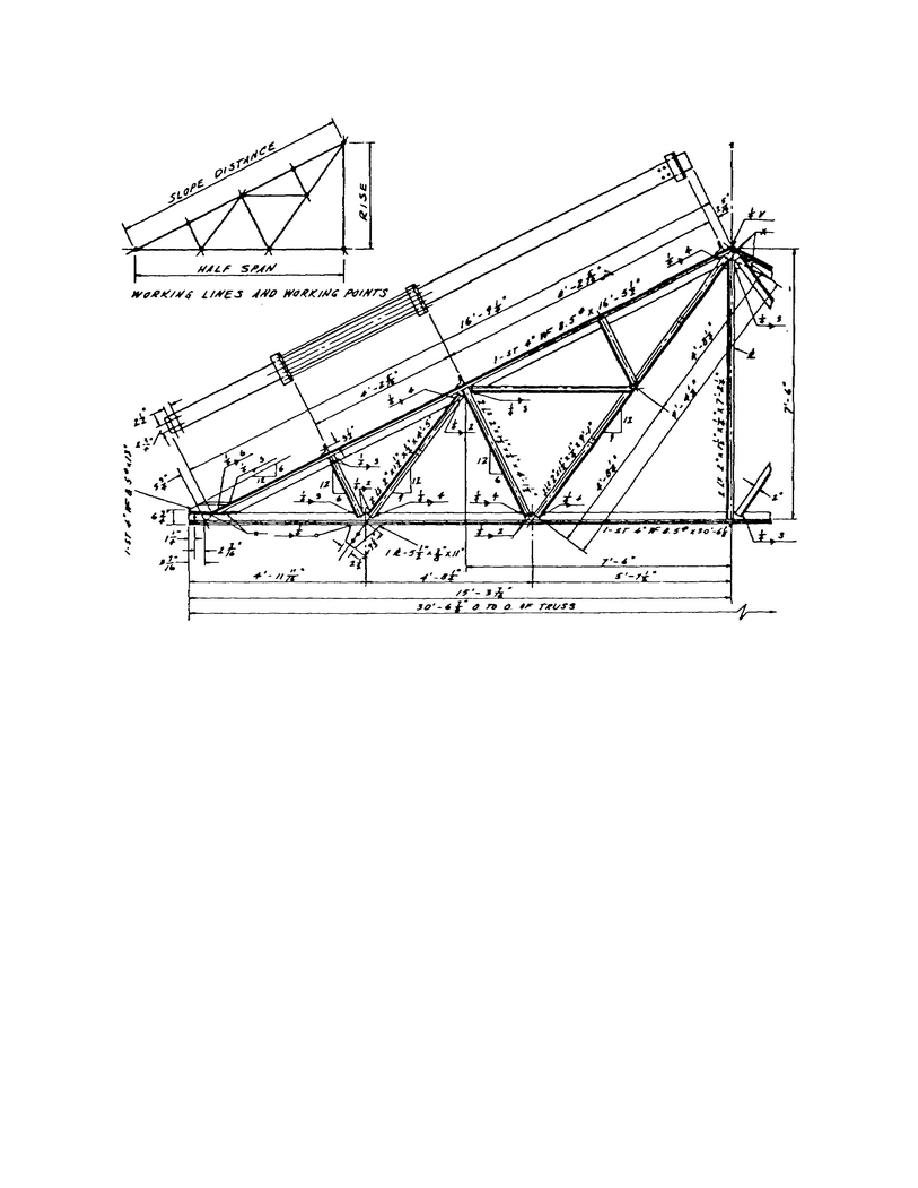
Figure 2-38. Typical welded steel truss.
from which all dimensions are given. This skeleton
members are sometimes shown in a horizontal
is usually the same as, or taken from, the designer's
position on the drawing. When shown in this
stress diagram. Generally, the skeleton diagram is
manner, the bottom of a vertical member appears at
drawn to a small scale on the shop drawing (fig 2-
the left (fig 2-37) and an inclined member is shown
38).
in the direction it would fall.
(2) Relative position of parts. Parts to be
(4) Scales. Scales of shop drawings vary
welded or riveted together in the shop are shown in
from 1/4 inch = 1 foot to 1 inch = 1 foot, depending
the same relative position (vertical, horizontal, or
upon the size of the drawing sheet as compared with
inclined, as in figure 2-38) they will occupy in their
the size of the structural member. Usually, two
assembled position in the structure. These parts are
scales are used in the same view, one denoting
not detailed individually, as is the practice for
length, and the other showing the cross-section at a
machine drawing. Note in figure 2-38 that due to the
larger scale than the length.
truss being symmetrical about each side of center,
only half of the truss need be shown. In such cases, it
b. General Plan. The general plan indicates
is always the left end that is drawn.
the location and gives the general features of the
structure and the ground upon which it is situated. It
includes the necessary data for constructing both the
(3) Long vertical or inclined members.
Long
vertical (columns) or inclined (braces)
substructure and the superstructure.
85


 Previous Page
