of the scale is further subdivided into 12 equal parts
as a reduced or enlarged print. This type of scale is
representing 1 inch each and the 3/32-inch
used with standard Army plans for frame structures.
subdivision into six equal parts representing 2 inches
b. Methods of sealing.
each.
(1) Architects' or engineers' scales.
(2) Engineers'. Engineers' scales (2,
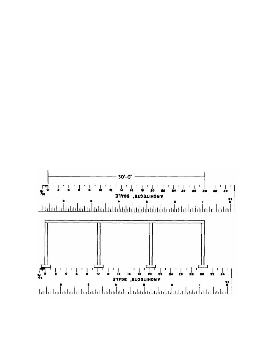
The method of scaling using architects' or engineers'
fig. 1-2) are divided into decimal graduations (10, 20,
scales is as follows:
30, 40, 50, and 60 divisions to the inch). These
scales are used for plotting and map drawing and in
(a) Determine the SCALE of the
the graphic solution of problems.
print from the notation given such as 1/4 inch = 1
foot-0 inches; 1 inch = 20 feet; 3/16 inch = 1 foot-0
(3) Metric. Metric scales (3, fig. 1-2)
inches and so forth.
are used in conjunction with the drawings, maps, and
so forth that are made in countries using the metric
(b) Select the corresponding scale
system. This system is also being used with
on the architects' or engineers' scale.
increasing frequency in the United States. The scale
(c) Using the proper scale,
is divided into centimeters and millimeters. In
measure the desired dimensions on the print. Figure
conversion, 2.54 centimeters (cm) are equal to 1 inch.
1-3 illustrates the use of an architects' scale. Note
(4) Graphic. Graphic scales (4, fig. 1-
that alining the 1-foot mark with the right hand end
2) are lines subdivided into distances corresponding
of the footing gives a direct reading of 1 foot, 9
to convenient units of length on the ground or of the
inches for the length of the footing.
object represented by the tracing. The graphic scale
(2) Graphic scales. The procedure
is placed in or near the title block of the drawing, and
normally used with graphic scales is as follows:
the relationship of its length to the scale of the
drawing is not affected if the drawing is reproduced
Figure 1-3. Scaling a dimension.
1-6


 Previous Page
