_______________________________________________________________________ Antennas
4-27. These impulses must be properly timed to sustain oscillations in the
antenna. The rate at which the waves travel along the wire is constant at
approximately 300,000,000 meters per second. The length of the antenna
must be such that a wave will travel from one end to the other and back
again during the period of 1 cycle of the RF voltage. Remember, the distance
a wave travels during the period of 1 cycle is known as the wavelength and is
found by dividing the rate of travel by the frequency.
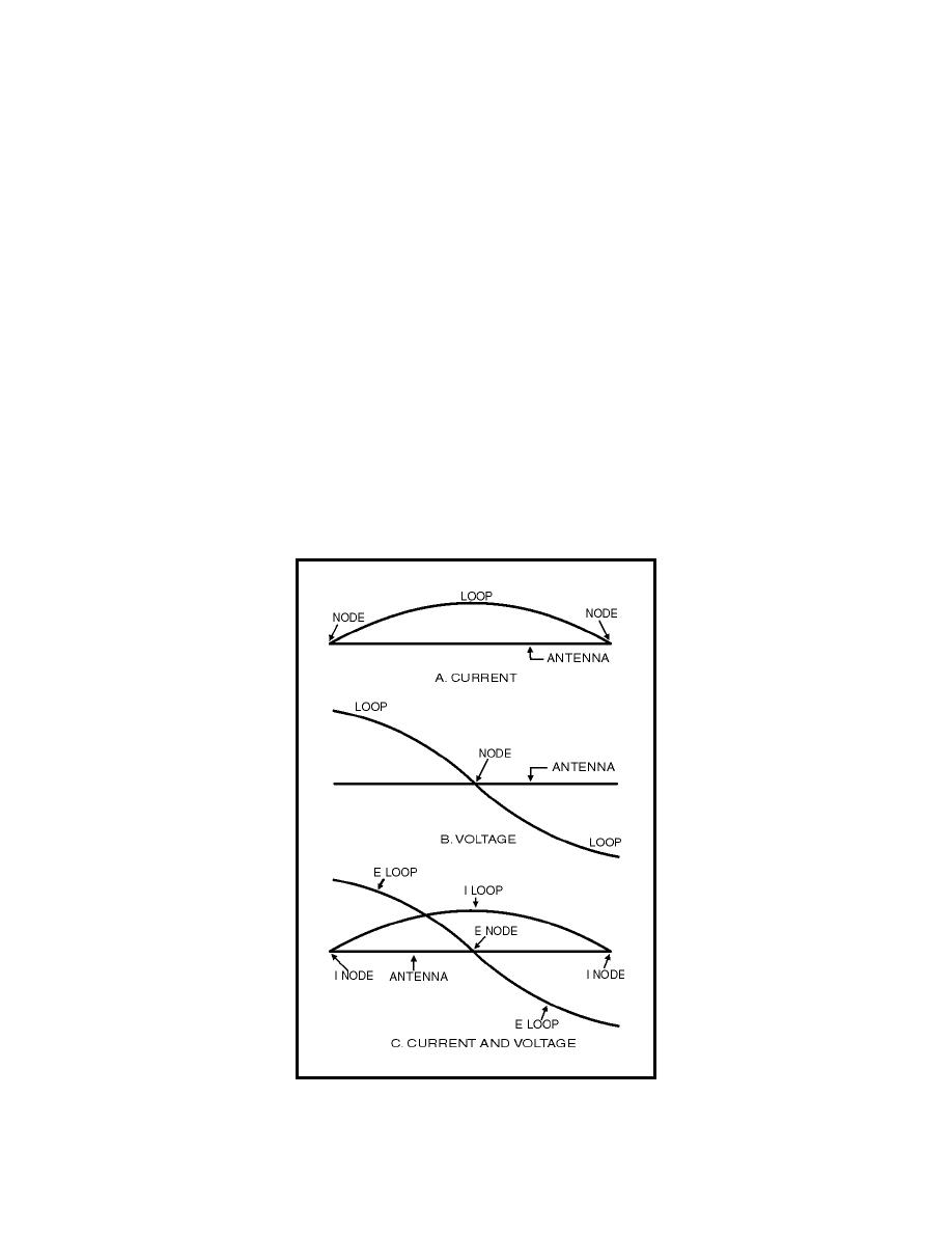
4-28. Look at the current and voltage (charge) distribution on the antenna in
figure 4-7. A maximum movement of electrons is in the center of the antenna
at all times; therefore, the center of the antenna is at low impedance. This
condition is called a standing wave of current. The points of high current and
high voltage are known as current and voltage loops. The points of minimum
current and minimum voltage are known as current and voltage nodes.
4-29. Figure 4-7, view A shows a current loop and current nodes. View B
shows voltage loops and a voltage node. View C shows the resultant voltage
and current loops and nodes. The presence of standing waves describes the
and forth in the antenna reinforcing each other and the electromagnetic
waves are transmitted into space at maximum radiation. When the antenna
is not at resonance, the waves tend to cancel each other and lose energy in
the form of heat.
Figure 4-7. Standing Waves of Voltage and Current on an Antenna
4-9


 Previous Page
