TC 9-62
FACTORS AFFECTING FREQUENCY RESPONSE OF AN AMPLIFIER
6-17. Chapter 5 mentioned that an audio amplifier is limited in its frequency response.
Remember that the frequency response of an AC circuit is limited by the reactive elements
(capacitance and inductance) in the circuit. This is caused by the fact that the capacitive
reactance and inductive reactance vary with the frequency. Therefore, the value of the
reactance is determined, in part, by frequency. The following is the formula for capacitive
reactance and inductive reactance:
1
XC =
2π f C
XL = 2π f L
6-18. If you ignore the amplifying device (transistor, electron tube, and so on), and if the
amplifier circuit is made up of resistors only, there should be no limits to the frequency
response. Therefore, a totally resistive circuit would have no frequency limits. However,
there is no such thing as a totally resistive circuit because circuit components almost
always have some reactance. In addition to the reactance of other components in the
circuit, most amplifiers use RC coupling. This means that a capacitor is used to couple the
signal into and out of the circuit. There is also a certain amount of capacitance and
inductance in the wiring of the circuit. The end result is that all circuits are reactive. Figure
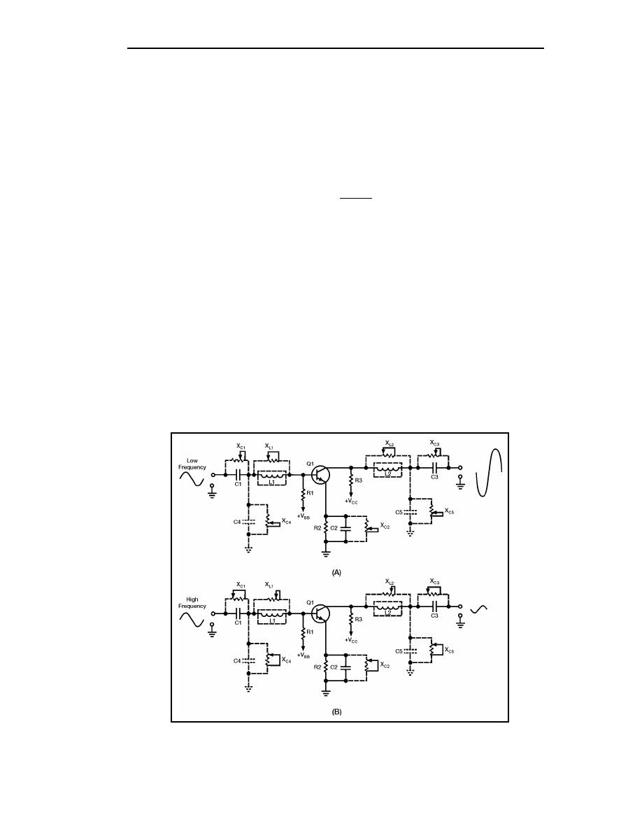
6-3 shows amplifier circuits with the capacitance and inductance of the wiring represented
as "phantom" capacitors and inductors. The reactance of the capacitors (XC) and the
inductors (XL) are shown as "phantom" variable resistors. View (A) shows the circuit with
a low-frequency input signal and view (B) shows the circuit with a high-frequency input
signal.
Figure 6-3. Amplifiers Showing Reactive Elements and Reactance
6-6
TC 9-62
23 June 2005


 Previous Page
