____________________________________________________________________________ Amplifiers
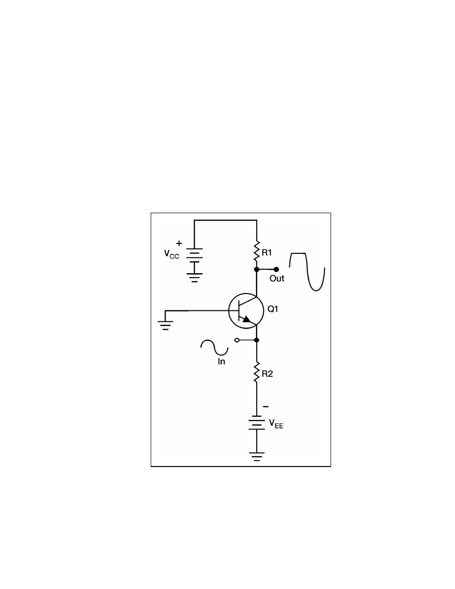
5-29. Notice that the output signal is distorted. The output signal no longer has the same
shape as the input signal. The portion of the output signal that appears to be cut off is
caused by the lack of current through the transistor. When the emitter becomes positive
enough, the transistor cannot conduct because the base-to-emitter junction is no longer
forward biased. Any further increase in input signal will not cause an increase in output
signal voltage.
5-30. Class AB amplifiers have better efficiency and poorer fidelity than class A
amplifiers. They are used when the output signal need not be a complete reproduction of
the input signal. However, both positive and negative portions of the input signal must be
available at the output.
5-31. Class AB amplifiers are usually defined as amplifiers operating between class A
and class B. This is because, class A amplifiers operate on 100 percent of input signal and
class B amplifiers operate on 50 percent of the input signal. Any amplifier operating
between these two limits is operating class AB.
Figure 5-5. Simple Class AB Transistor Amplifier
Class C Operation
5-32. Figure 5-6 shows a simple class C amplifier. Notice that only a small portion of the
input signal is present in the output signal. Since the transistor does not conduct except
during small portions of the input signal, this is the most efficient amplifier. However, it
23 June 2005
TC 9-62
5-7


 Previous Page
