TC 9-62
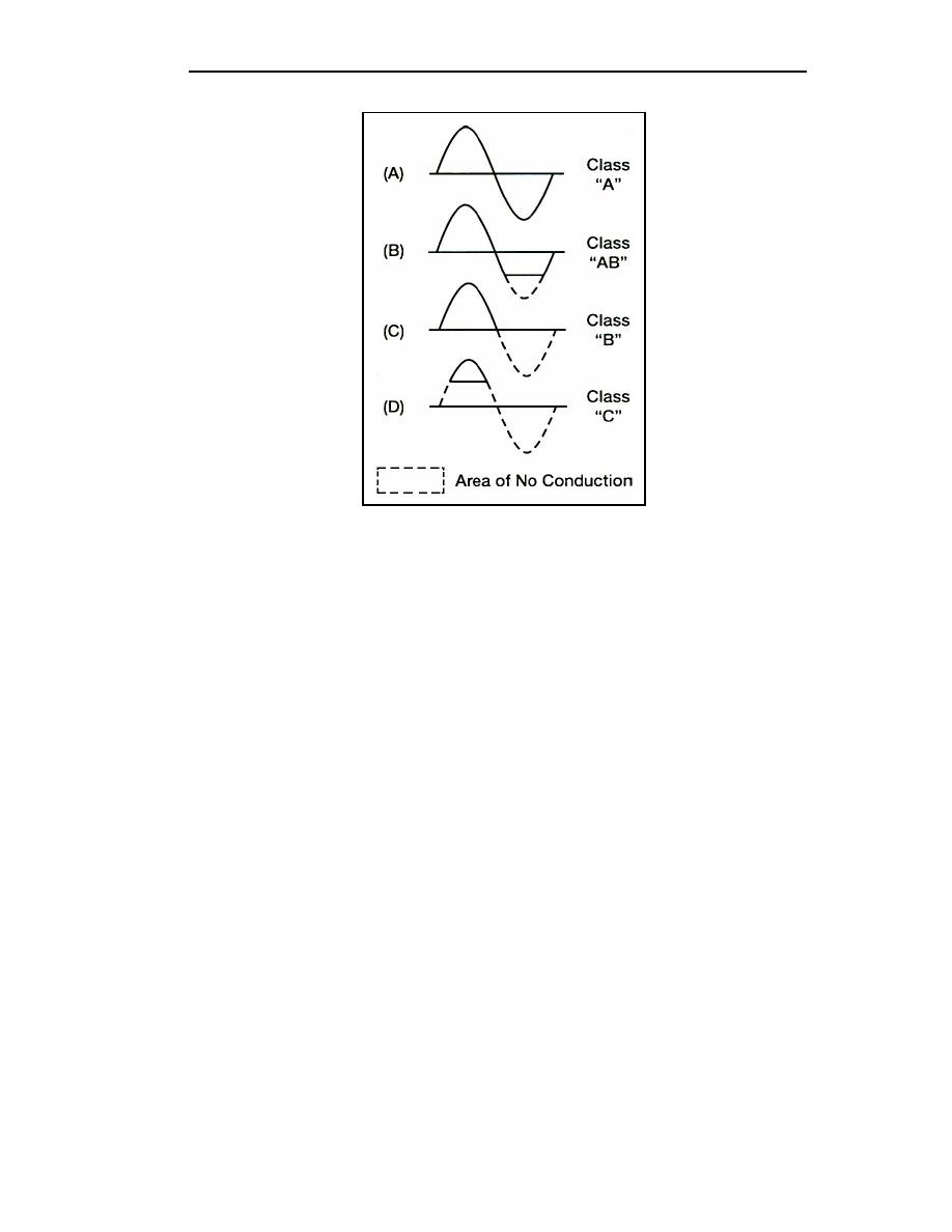
Figure 2-17. Comparison of Output Signals for the Different Amplifier
Classes of Operation
Class A Amplifier Operation
2-53. Class A amplifiers are biased so that variations in input signal polarities occur
within the limits of CUTOFF and SATURATION. For example, in a PNP transistor if the
base becomes positive with respect to the emitter, holes will be repelled at the PN junction
and no current can flow in the collector circuit. This condition is known as cutoff.
Saturation occurs when the base becomes so negative with respect to the emitter that
changes in the signal are not reflected in collector-current flow.
2-54. Biasing an amplifier in this manner places the DC operating point between cutoff
and saturation. This allows collector current to flow during the complete cycle
(360 degrees) of the input signal, thereby providing an output, which is a replica of the
input. Although the output from this amplifier is 180 degrees out of phase with the input,
the output current still flows for the complete duration of the input (see Figure 2-17, view
(A)). The class A operated amplifier is used as an audio and RF amplifier in radio, radar,
sound systems, and so forth.
Class AB Amplifier Operation
2-55. Amplifiers designed for class AB operation are biased so that collector current is
zero (cutoff) for a portion of one alternation of the input signal. This is accomplished by
making the forward-bias voltage less than the peak value of the input signal. By doing this,
the base-emitter junction will be reverse biased during one alternation for the amount of
time that the input signal voltage opposes and exceeds the value of forward-bias voltage.
Therefore, collector current will flow for more than 180 degrees but less than 360 degrees
of the input signal (see Figure 2-17, view (B)). Compared to the class A amplifier, the DC
operating point for the class AB amplifier is closer to cutoff. The class AB operated
amplifier is commonly used as a push-pull amplifier to overcome a side effect of class B
operation called crossover distortion.
2-18
TC 9-62
23 June 2005


 Previous Page
