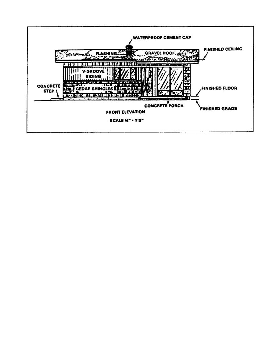
Figure 1-7.
Accent lines
c. Floor Plan. A floor plan is a crosssectional view of a
building. The horizontal cut crosses all openings, regardless of
their height from the floor. The development of a floor plan is
shown in Figure 18, page 110. Note that a floor plan shows the
outside shape of the building the arrangement, size, and shape of the
rooms; the type of materials; and the length, thickness, and
character of the building walls at a particular floor. A floor plan
also includes the type, width, and location of the doors and windows;
the types and locations of utility installations; and the location of
stairways. A typical floor plan is shown in Figure 19, page 111.
(1) Drawings and Specifications. Drawings and specifications
inform the contractor, owner, material dealers, and tradespeople of
decisions made by the architect and owner of the structure. Floor
plans are usually drawn to scale (1/4" = 1' or 3/16" = 1'). Symbols
are used to Indicate different types o fixtures and materials.
NOTE: Electrical, heating, and plumbing layouts are either on the
floor plan or on separate drawings attached to the floor plan.
(2) Floor Plan details. Detailed drawings may appear on the
plan or on separate sheets attached to the plan. When detailed
drawings are on separate sheets, a reference symbol is drawn on the
floor plan. A door and window schedule is presented on the plan (see
sample on Table 12 on page 110 is a sample showing the information
given on the schedule.
1-9
EN5155


 Previous Page
