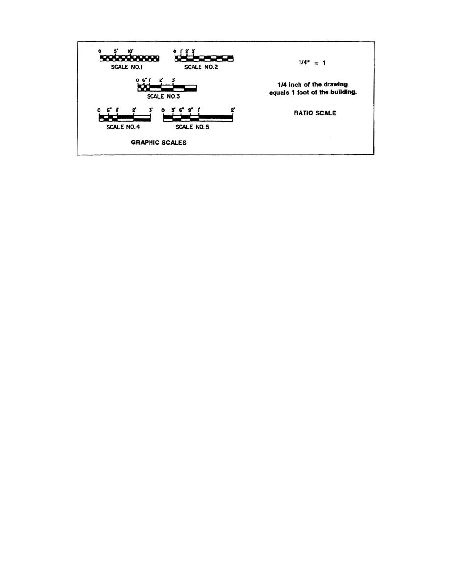
Figure 1-2.
Graphic and ratio scales
d. Lines on Drawings (Figure 13, page 14). Line conventions
most often seen on working drawings are
(1) Visible Lines. A heavyweight unbroken line is used for the
primary feature of a drawing. For drawings of objects, this line
convention represents the edges, the intersection of two surfaces, or
the surface limit that is visible from the viewing angle of the
drawing. This lines is often called the outline.
(2) Hidden Lines. A medium weight line of evenly spaced short
dashes represents an edge, the intersection of two surfaces, or the
surface limit which is not visible from the viewing angle of the
drawing.
(3) Center Lines. A thin (light) line composed of alternate
long and short dashes of consistent length is called a centerline.
It is used to signify the center of a circle or arc and to divide
object into equal or symmetrical parts.
(4) Dimension Lines. A solid, continuous line terminating in
arrowheads at each end. Dimension lines are broken only to permit
writing in dimension. On construction drawings, the dimension lines
are unbroken. The points of the arrowheads touch the extension lines
which mark the limits of the dimension. The dimension is expressed
in feet and inches on architectural drawings and in feet and decimal
fractions of a foot on engineering drawings.
(5) Extension lines. An extension line is a thin (light),
unbroken line that indicates the extent of the dimension lines. The
extension line extends the visible lines of an object when it is not
convenient to draw a dimension line directly between the visible
lines. There is always a small space between the extension line and
the visible line.
1-3
EN5155


 Previous Page
