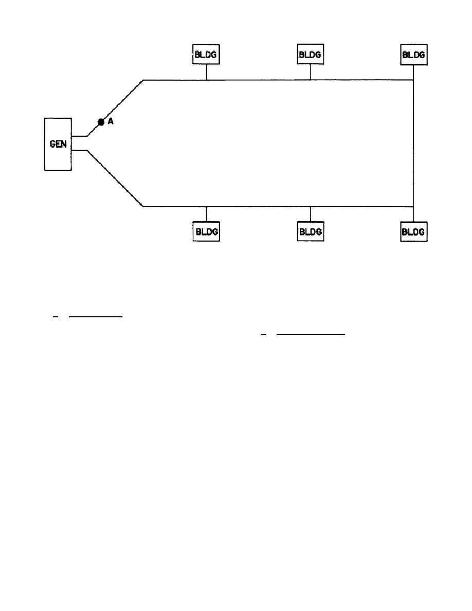
NOTE:
WIRE SHOWN REPRESENTS TOTAL NUMBER OF WIRES
Figure 2.
Ring system.
within the installation.
They are
time to construct than the radial
known as the ring and radial layouts.
system.
For this reason, in the
theater of operations radial systems
a. Ring layout.
A ring layout is
are used exclusively.
one in which power is supplied to a
facility from more than one direction
b. Radial
layout.
The
radial
as shown in figure 2. The single wire
layout is one in which a mainline is
shown represents the total number of
established through the approximate
wires in the system whether it be the
center of an installation and branch
lines are run from the main to the
two wires of a 1 2W system or the
various facilities to be served.
A
four wires of a 3 4W system. It can
typical radial layout is shown in
be seen that a break in the wires at
figure 3. The primary disadvantage of
point "A" will not cause complete
the radial layout is that a break of
power failure since power may still be
wires at point "B" results in a
distributed through the lower section
complete
loss
of
power
to
all
of the ring.
Thus a ring system has
facilities in the installation. Thus,
an inherent resistance to complete
the radial system is more susceptible
loss of power to all facilities.
to extreme weather conditions and
Faults in the circuit can be isolated
sabotage.
However, since the radial
and repaired without large disruption
system
requires
considerably
less
of service.
In addition, the ring
material,
manpower,
and
time
to
layout normally distributes power with
construct, radial systems are used in
less
voltage
drop.
The
primary
the theater of operations.
disadvantage of the ring system is
that it requires more material and
2-3


 Previous Page
