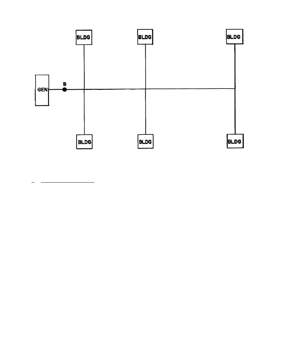
NOTE:
WIRE SHOWN REPRESENTS TOTAL NUMBER OF WIRES
Figure 3.
Radial system.
c. Wiring layout plan.
After the
feeder.
Sometimes a service wire to
required generators have been selected
one or more structures may also be
and located, a plan is drawn showing
connected to the feeder.
The branch
the
proposed
arrangement
of
the
or service wires will usually be of a
wiring.
The plan should show the
smaller size because of the smaller
generator site; the location of poles;
demand
requirements
of
the
few
all branches and sections of wires;
buildings which they serve.
The
and all the structures to be served.
layout plan should also show the
The
poles
should
be
spaced
length of each section of feeder wire
approximately 150 feet apart. In some
and the distances between points where
cases, wires under 240 volts will be
power is taken off.
The total demand
strung from building to building.
In
load at each point where power is
general, the feeder wires will radiate
taken
off
from
the
feeder
is
from the generator towards various
calculated and shown.
areas of structures for distances of
3.
DISTRIBUTION SYSTEM BALANCING
up to 1,500 feet in small systems
generating up to 240 volts.
If any
buildings are more than 1,500 feet
In
lesson
1
the
types
and
from the generator, attempts should be
functions
of
generators
were
made
to
move
the
generator,
if
discussed.
It was seen that loads
possible, so that all structures to be
may
be
connected
between
a
served are within the 1500 foot limit.
At some convenient pole, branch wires
(fig 4) are usually connected to the
2-4


 Previous Page
