
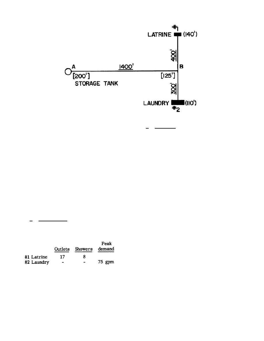
Figure 16.
Water distribution system layout.
connection elevations, and numbers in
b. Solution.
For latrine #1 there
brackets [ ] are main elevations.
are
17
outlets
and
8
showers.
Referring to figure 13, enter the left
19. CHECK FOR EXCESS PRESSURE
column at 17 outlets.
Connect this
point to the point on the right column
From paragraph 14, wherever the line
corresponding to eight shower heads.
is more than 231 feet below the
These two points are shown connected
storage tank, the pressure will exceed
on the figure, with the connecting
100 psi. For the system in figure 16,
line intersecting the center column at
the tank elevation is 200 feet while
a peak demand of 25 gpm (gallons per
the lowest point in the system is the
minute).
The
peak
demands
for
service connection for No. 2 laundry
buildings one and two are shown below:
at 110 feet.
Therefore, the maximum
elevation difference is 90 feet, so
#1 Latrine
25 gpm
the static pressure in the line will
not exceed the safe working pressure.
#2 Laundry
75 gpm
20. FLOW ESTIMATION
The
peak
flow
in
the
lines
is
determined next. The line from A to B
a. Requirement.
With the numbers
(main AB) must be able to carry the
of outlets and showers shown below,
peak demand for both buildings. Hence
determine the peak demand for each
the peak flow in line AB is the total
building and the peak flow in the
peak demand for the buildings, or 100
lines.
gpm. The peak flows in the lines are
then as follows:
Main AB:
100 gpm
Branch B1:
25 gpm
Branch B2:
75 gpm
3-21

 Previous Page
