Lesson 2/Learning Event 2
Learning Event 2
DESIGN CURVES AND LOAD
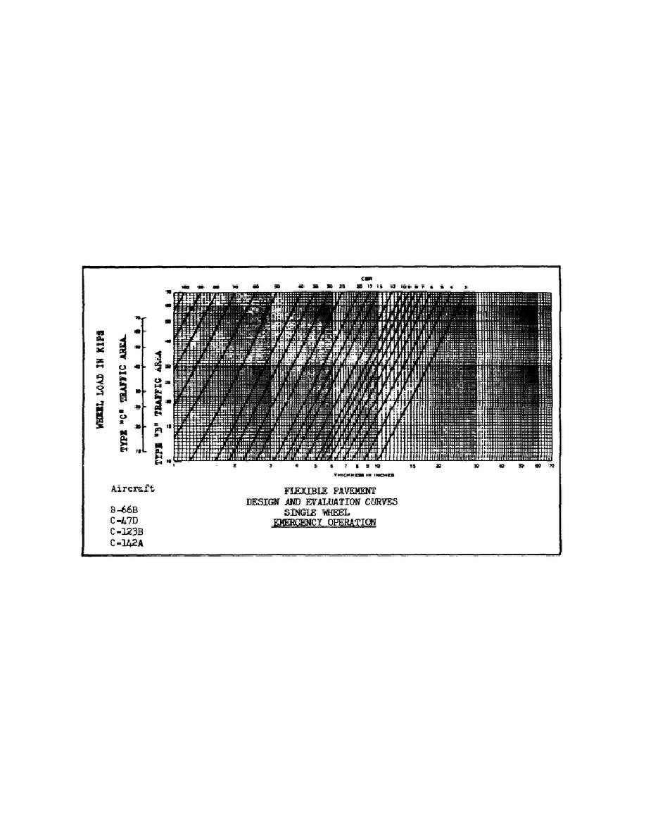
The design curves represent the recommended required thicknesses of stable material above the layer
being considered. Each type of aircraft in the Air Force inventory has an assigned flexible pavement
design and evaluation curve. These curves are shown in Figures D-25 through D-37, Appendix of this
subcourse. To determine which design curve to use you must know the type of aircraft and the
operational category of the airfield. For example, if you were constructing an emergency operational
airfield for use by C-123B aircraft, you would select the design curve shown in Figure 13.
FIGURE 13
More information on selecting design curves can be found in TM 5-330.
Select Design Gear Loads in KIPS
A design gear load for each type of aircraft in the Air Force inventory has been established. These gear
loads are shown in tips (1 kip = 1000 pounds). The established gear load for each type of aircraft is
listed in Table 13-10 (located in the appendix). Using Table 13-10, select the correct gear load for a C-
141A aircraft. You should find that the gear load is 149,500 pounds or 149.5 kips. Table 13-10 also
shows the recommended minimum thickness of pavement and base course for a flexible pavement. For
example, for an Air Force airfield, which is fully operational with a
43


 Previous Page
