are actually dropped 6.8 feet as shown on figure 3-23
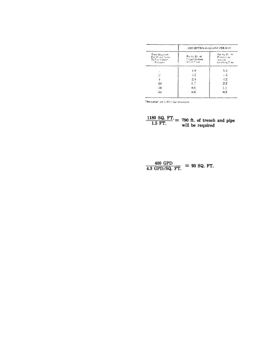
Table 3-1. Soil Absorption Rates
before connection is made to the main sewer line.
Look carefully at each section of the main sewer and
note the numbers 0.01, 0.009, 0.125, 0.005. These
numbers indicate the grade of each section and are
calculated as follows: From the profile, you can read
the inlet elevation of manhole No. 1 as 193.2 feet
and the inlet elevation at manhole No. 2 as 192.05.
The distance between these two points is given as
11.46 feet. Therefore, the grade is (193.2-192.05)
114.6 = 1.15 114.6 = 0.01, or a 1-percent grade, or
a 1-foot drop in 100 feet. It was stated in paragraph b
preceding that although the size of the septic tank
could be read from the plan view, the actual elevation
of the base could not be determined from the plan
If trenches are 18 inches wide,
view. From the profile view you can now read the
required depth of the footing for the septic tank. It is
shown to be at an elevation of 187.2 feet or 12.8 feet
below the floor level of the buildings. One final
point of major importance that cannot be completely
(3) Example 2. A leaching tank must
read from either the plan or profile views is the
handle 400 gallons per day (GPD) and the average
extent, or area, of the subsurface sand filter. As was
time noted in the soil test is 2 minutes. From table 3-
noted earlier, this must be determined by a soil
1, this corresponds to an absorption rate of 4.3
absorption test which is performed as follows:
gallons per day per square foot.
(1) Soil absorption test procedure. Dig
test holes (at least three) 1 foot square to the
proposed depth of the tile and fill them with water to
a depth of 1 foot. After the water has seeped away,
(4) Capacity. The following information is
and while the bottom of the holes are still wet, refill
general in nature and will have been taken into
the holes to a depth of 6 inches. Note the average
consideration when the plans were made. The
time required for the water level to drop one inch and
necessary capacity for a sewerage system is normally
compute the necessary percolation area from the data
based on handling 25 gallons per day per man, or 50
in table 3-1.
gallons per day per bed for hospitals. A facility
housing 500 troops, therefore, would require sewage
(2) Example 1. A sand filter must handle
disposal facilities capable of handling 12,500 gallons
2,000 gallons per day and the average time noted in
per day. A 100-bed hospital would require disposal
the soil absorption test is 10 minutes. From table 3-1,
facilities capable of handling 5,000 gallons per day.
this corresponds to 1.7 gallons per day per square
Septic tanks must normally be capable of detaining
foot.
sewage for 24 hours. Sewer piping is usually
designed for capacities of three times the average
flow in order to handle peak loads, but pipe less than
6 inches in diameter should not be used for main
sewers, and the rate of flow should not be less than 2
feet per second when full or half full to prevent
clogging regardless of the capacity required. The
minimum velocity is usually specified as 1.5 feet per
second.
131


 Previous Page
