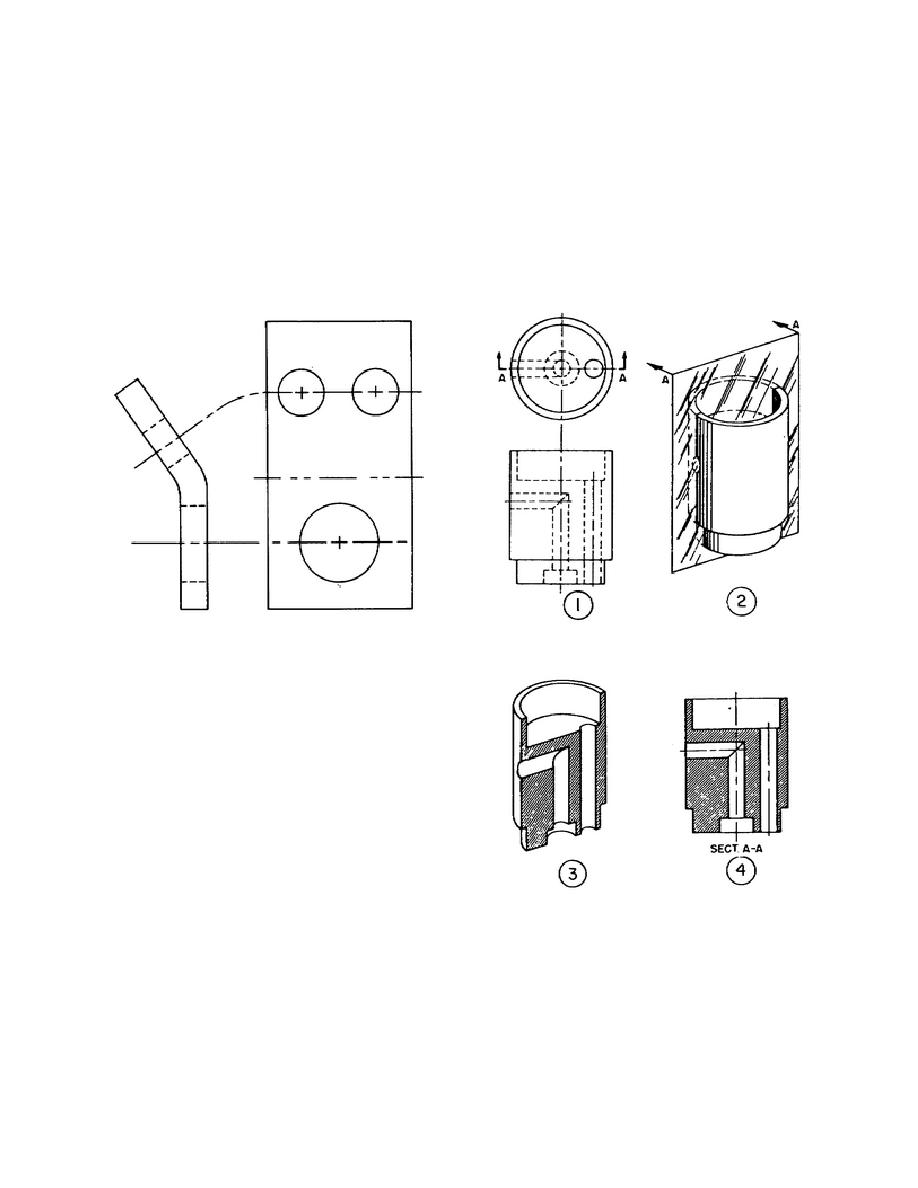
b. Rotation. Occasionally, if no confusion
a different slant or style of section line is used for
will result from the practice, a separate auxiliary view
each part. All rules of projection apply, but hidden
is omitted and a side or top view is provided, drawn
lines complete understanding of the view. Notice
as if the object was bent to bring the slanted surface
how the cutting plane is shown on a drawing as
parallel to the drawing plane (fig 1-18). This is
Illustrated in [1] figure 1-19. The cutting plane in [2]
called a rotation, and the fact that it has been done
illustrates where the imaginary cut is made. The
will be indicated in some manner on the drawing. In
object as it would look if were cut in half is shown in
figure 1-18, for example, the fact that one view is
[3]. The section view as it would appear on a
higher than the other, plus the curvature of the upper
drawing is shown in [4].
center line shows immediately that the right hand
view is a rotation.
Figure 1-18. Rotation.
c. Sections. Section views are used to give a
clear view of the interior or hidden features of the
object which normally cannot be clearly observed in
conventional outside views. A section view is
obtained by cutting away part of an object to show
the shape and construction at the cutting plane. The
most common position of the cutting plane is through
the longest dimension, or main longitudinal axis and
parallel to the front view as shown in figure 1-19.
The cutting plane may be drawn parallel to any plane
of projection if it shows the required features of the
object. When section views are drawn, the part that
is cut by the cutting plane is marked with close
spaced, parallel (section) lines. The section lines
Figure 1-19. Action of the cutting plane.
indicate the surfaces which were created by the
cutting plane and which do not exist on the uncut
object. When two or more parts are cut in one view,
16


 Previous Page
