TM
5-811-1/AFJMAN
32-1080
c. Cable ampacity. The current carrying capaci-
ing cables. Calculations of the position effect indi-
ties of cable will be in accordance with ampacities
cate that, to equalize operating temperatures, full-
given in the NEC and IEEE/ICEA publications.
load ratings of cables appropriate for isolated
There are many factors taken into account in
(one-way) ducts should be decreased for multiple
duct banks. For example, in an eight-way-duct
determining these allowable ampacities such as
bank the recommended full-load percentage de-
operating temperatures, soil effects, shielding
losses, and conductor configurations, but the vari-
crease for each corner duct is 95 percent and for
each interior duct is 83 percent giving an average
ables which cause the most concern are circuit
loading and location in a duct bank. Because of
load percentage decrease of 89 percent. This derat-
load diversity, peak demands for cables in a duct
ing still allows provision for loads in excess of the
bank will not occur concurrently in most cases.
normal feeder capacity usually found on military
installations, as the summation of feeder capaci-
This diversity factor will be taken into account
when computating expected heat build-up in a
ties is generally from three to eight times the
duct bank. Heat dissipation from a cable is also
overall capacity of a main electric supply station.
d. Power cable joints. A splice which connects
influenced by the position occupied by the cable in
cables rated 2.5 kV and above is known as a power
a duck bank. Cables in duck bank corners dissi-
pate heat more effectively than cables in interior
cable joint. Cable joints are composed of connectors
ducts, because of the greater soil dissipating area
to join two or more cables for the purpose of
and the smaller heat contribution from neighbor-
providing a continuous electric path plus necessary
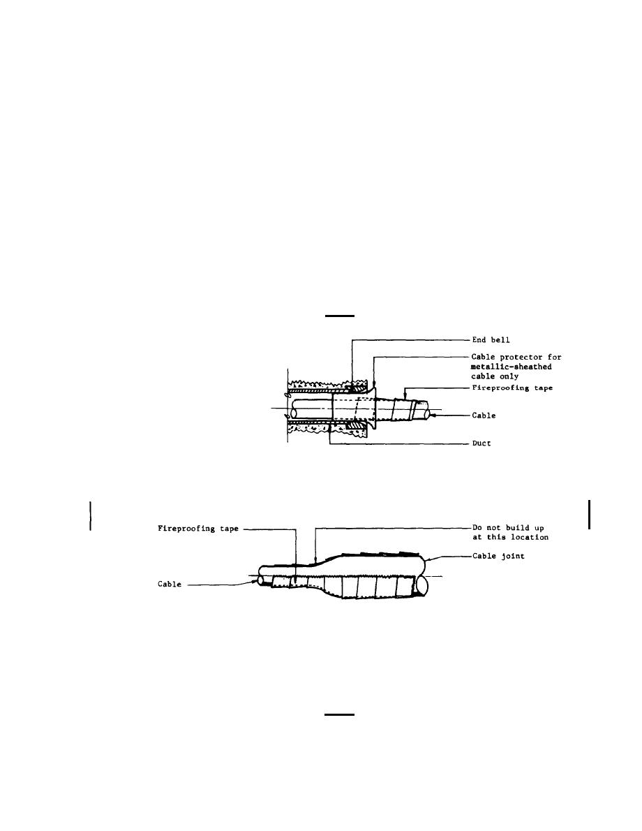
DUCT ENTRANCE
CABLE JOINT
REQUIREMENTS
Fireproof only medium-voltage circuits (over 600-volts).
Fireproof cables their entire length within
the manhole and Into the duct entrance as indicated.
US Army Corps of Engineers
Table 7-1. Rated Conductor Temperatures.
7-3


 Previous Page
